Showing posts with label deck bearers. Show all posts

Wednesday, 9 September 2015

Deck Building. Building a flight of stairs

Now that I have become the stair master by building the two step wraparound stairs on the back landing, I now have to undertake the far longer set of stairs that run from the deck down to the lawn area. This is my first try at a full set of stairs so it's really all new to me. There's a really good instruction on stair building over at instructibles.com which was great for a newbie like me.

The first thing required is to figure out the rise and the run of the slope that the steps are to go down. The rise of a flight is the vertical distance between the floors or landings connected by the flight. The individual rise is the vertical measurement from top of tread to top of tread. The run is the horizontal distance covered by the entire staircase, or technically the distance from the trimmer face to the front of the first steps nosing. Using a long piece of straight timber clamped to the existing joists, and a plumb bob and tape measure, I obtained the rise and run.

With this data in hand I then headed over to the stair calculator web site and plugged the measurements into the X and Y fields. I then start playing around with the number of steps and the width of the stinger, until I am happy with the height of the step and depth of the tread, and I then have the measurements for the required stringers.

Using these dimensions and a large framing square with stair gauges, I draw out the stair pattern on the stringer just like the photo below.


Once you have the stringer marked out you can attack it with a combination of a circular saw to do the long cuts and a jigsaw the finish the corners. Be as accurate as possible with the first stringer as it will become the template for the rest of them to follow. In my case I need five stringers.

MEASURE TWICE, CUT ONCE is the old carpenters rule of thumb. Stick to it.


Before I can lay any kind of woodwork in I need to create a concrete pad for the bottom step to attach to. Per the photo below, once I had cut the first stringer cut I used that to help measure and position the form for the pad.

Measuring up for the form

With a pair of stringers cut, I positioned them on the outside and clamped them against the joists to hold them in place, then measured and levelled everything before mixing and pouring the concrete for the pad.

Checking and preparing for concrete

Once the concrete was cured and the form removed, I then clamped on four stringers just to make sure I hadn't missed anything! As you can see below, it all came out level.

Checking everything for level

The picture below shows all the stringers attached and in place, I bolted the stringers to the concrete pad using galvanised steel L brackets with Loxins to go into the concrete, and diagonally set coach bolts through the stringer into the bracket.

All stingers attached and bolted in place.

To attach the top of the stringers to the deck I used exactly the same method I utilised to attach the small two step stringers to the landing in my previous post, by boxing them in. Below shows all the stringer top steps locked in tight between the noggin and front ledger.


Top of stringers boxed in screwed down

So that was it! Per the photo below the entire deck frame was now finished (or so I thought at the time!) and ready for the council building inspector to give it the big tick!


Entire deck frame completed and ready for the council engineer's inspection

So I booked in the inspection and the engineer came over to have a look. He's actually quite a nice guy who is, after all, only looking after the safety of myself and my BBQ guests! There was a couple of things he wasn't happy with in the frame:
  1. The width of the open string on the landing steps he felt was a little too narrow and asked that they be in filled underneath to support the step (see my previous post on building the landing)
  2. The stringers were too long a run to go unsupported. Even though they were within code, he felt there was going to be too much flex in the steps and that I should underpin them in the middle with a bearer to support them.
  3. Owing to the length of the stinger, he wanted to see the top connection into the noggin reinforced with some builders strapping to support them.
They were all worthwhile observations that I happily agreed to rectify! I was at last getting some value out of a local council service! Building is so much easier to deal with than planning (you can catch up on my council planning nightmare post here).

So I got to work, and using the pick and post hole digger, started in on digging post holes for posts to support the new bearer. Below shows where they will go in.


And here I was thinking I was done digging bloody holes!

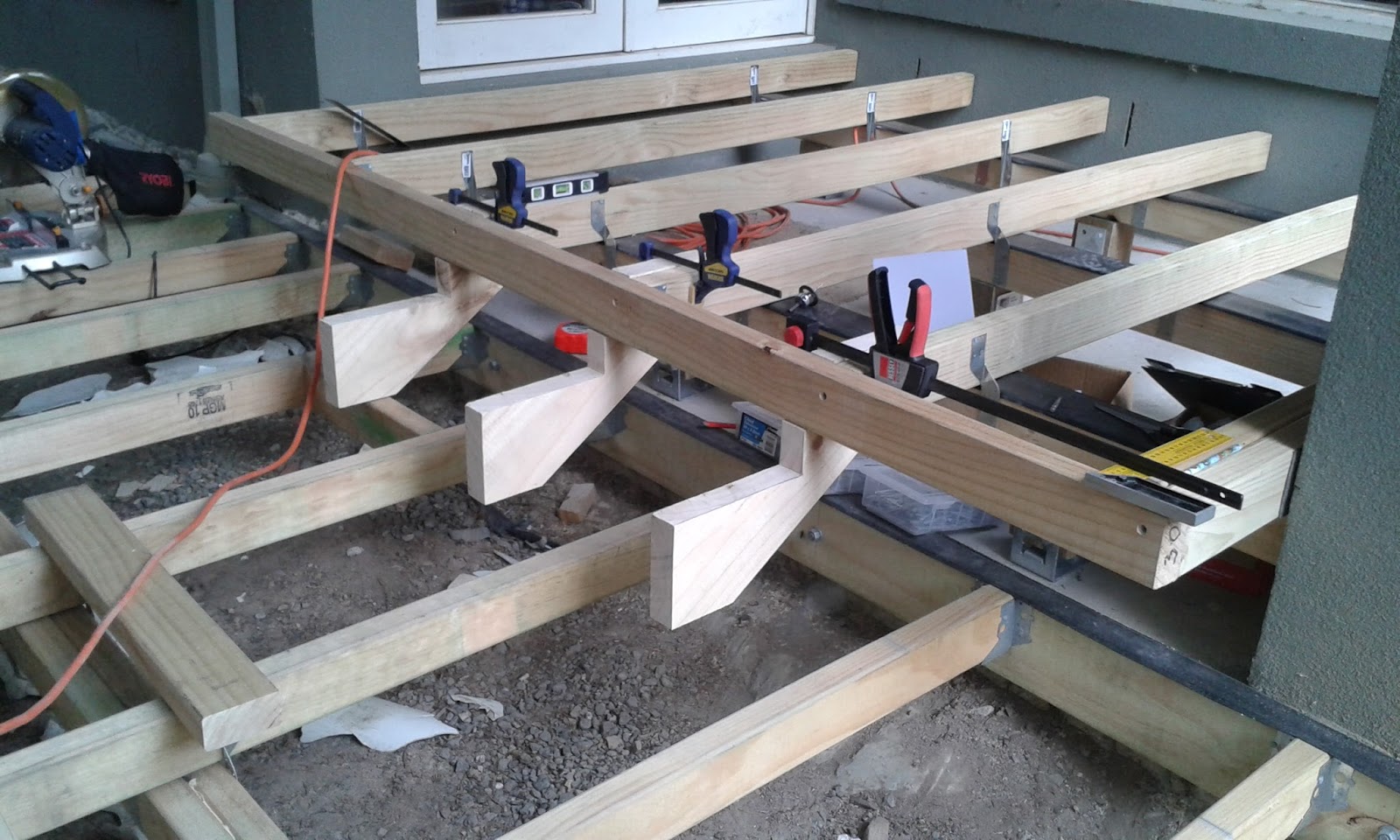
Because everything was already in place and I was loath to dissemble, I used a slightly different method of putting in the bearer. Normally I would concrete in the posts, let it set, then attach the bearer etc. 

In this instance I dropped the posts into the empty holes, passed through the bearer and bolted it onto the posts. I then clamped the whole assembly to the underside of the stringers where I had cut a notch to accept the top of the bearer. Once this was all in place I then poured the concrete into the holes.

Once the concrete was set I then just removed the clamps and screwed the stringers into the bearer. Job done!


Completed supporting bearer in place

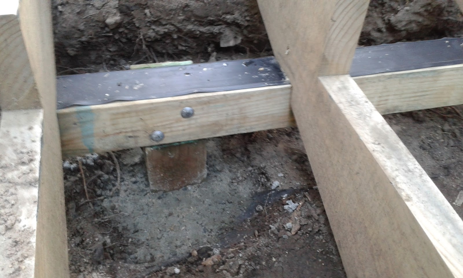
Below is a closer view of the bearer notched into the bottom of the stringer and screwed in place.


Notched stringer screwed into the bearer

The whole assembly was now really, really, really solid as a rock. Not an ounce of bounce!


The post bone connects to the, bearer bone, the bearer bone connects to the, stringer bone

The last thing required was to add the builders strapping to the underside of the top of the stringer and up the back of the noggin that holds the stair assembly in place. 

Trust me it wasn't an easy exercise, as I wasn't prepared to disassemble everything to attach the strapping to the bottom of the stringer. Some judicious digging was required so I could get a hammer in at the right angle to knock in the galvanised clouts!


Stringers strapped in nice and tight!

So the stair frame was now completed to the satisfaction of the council, and myself. After sending off the photos of the extra work the council was happy to sign off the frame stage of the deck. Happy days!


The finished stair frame signed off!

Next up we get to into selecting and laying the decking boards!
If you want to jump ahead to finishing up the stairs you can have a look here.

Sunday, 30 August 2015

Deck building. Preparing for the landing!

The frame for the main section of the deck is completed which overall was a reasonably straight forward affair, so now it's time to work on the trickier parts! Please put your chair in the upright position and ensure that your tray-table is securely stowed as we prepare for the landing.

To join the deck to the back door there's a landing required, and two steps from the landing down to the main deck proper. The steps at the front protrude 60 cm out past the line of the house and wrap around providing steps on three sides with the deck boards mitre joined on the corners. The steps to the side are straight steps within the line of the house.

The plan below shows the posts, bearers and joist locations.

Please put your tray table into the upright position and prepare for landing!

The bearers, like the main deck, are made up of dual 90 x 45 mm MGP10 treated pine nailed together. The 100 x 100 mm treated pine posts were fixed to the concrete using Pryda bolt-down post anchors. Mounting and assembly was pretty straight forward.

Bearers in place

Once the bearers were complete, the 90 x 45 mm MGP10 treated pine joists were laid across them. For the first time in 8 years we could now walk out the back door without the BIG step!

Joists laid

The final part of the joist assembly was to fix a joist across the front with 90 mm treated pine screws, to which the step stringers will be attached (see below).

To calculate the stringers I used the stair calculator function from the Russian based 'construction calculator' site (check out my resource page for this and other on-line tools) to get the dimensions of the stringer, and from this I created a cardboard template which I used to mark out onto the timber 
the stingers to be cut. To fix the stringer to the deck I added an extra cut of 90 x 45 mm into the front of the top step, so that it can slot in under the front joist.

In the picture below you can see I have clamped three of them to the front joists to check for size and position.

Testing the steps

To fix the stair stringers to the deck a 'noggin' needs to be added behind the end of the stringer to hold it in place against the front joist.

Step 1 mark it up. The noggin fits between the joists, so using the cut stringer place it against one side of the joist and mark the back end of the stringer on the joist, repeat on the other side. This is where the front edge of the noggin needs to line up on the joists.
Step 2 make the noggin. I used a piece of 90 x 45 mm MGP10 treated pine (aka joists offcuts!) and a pair of joist hangers to fit and hold the noggin between the joists. 
Step 3 slip in the stringer. Slide in the top of the stringer up and in between the noggin and the front joist, lining it up with the joist from the bottom level
Step 4 screw it all in. Get a small level and make sure everything is plumb, then secure the stringer in place with 110 mm screws through the front joist and the back noggin into the stringer. Lastly secure the bottom of the step by screwing the stringer bottom at an angle into the bottom joist.

Below shows the first step stringer mounted and secured.

First step in place

Repeat the process for each step stringer until you have one lined up with every bottom joist. Now when it comes to corners things get a little tricky. 

The corners need to have a double stringer put in place, so you have somewhere the attach the ends of the decking boards on either side of the step. The ends of the stringers also need to fit in the same corner spot as all the other stringers on the corner, and things can get a little cramped. 

To get around this I made the top of the assembled corner stringer short on top (as only the step itself needs to support weight) so it could fit in. I then relied on a noggins placed underneath the stringer, between the bottom joists, to hold the stringer in place and support the step. By doing this I didn't have to worry about supporting it at the top like the other straight stringers.

Below you can see the assembled corner.

These corners are pretty tricky!

Below is a close look at the assembled corner and the two noggins I added in underneath to support the step at the front and rear. The corner stringer was is screwed into the joists and the noggins to hold everything nice and secure.

It's a tight squeeze to fit it all in

Below is the progress in assembling the stairs.

The landing is taking shape

Below shows the final assembled front step frame. Here you can see the noggins that support the corner step on the other end. All this work will allow the steps to wrap around and have nice mitred joins on the corners.

Front steps frame completed!

For the side steps there were no joists to support the bottom of the stringers, so I used Klevaklip adjustable joist supports. These are a great invention for mounting 45 mm timber into a concrete base, and can be used where you are building over concrete and don't have enough clearance for a bearer. You fix the base plate into the concrete with two bolts of sufficient length protruding, and then fit the support bracket to the bolts using a set of nuts and washers to hold them at the required height. This makes setting the height of the support fully adjustable.

The stringers were fitted to the deck using the same method as the front steps, by boxing in the top rear of the stringer. Below you can see I have clamped up the stringers to the front joist so I can set the height needed for the supports.

Fitting in the side steps

Below is the completed side step. I had to change the cut into the step and move it back about an inch into the rise because of the narrow width back to the next joist.

Side steps completed

Below is the completed landing frame and steps.

Landing completed

The council inspector was overall pretty happy with the landing frame, but thought that the "throat" of the stringer looked a little narrow, so asked me to infill behind the stringer to support the step. It wasn't a bad suggestion and reasonably easy to achieve, so I reused the offcuts from the steps to make the fillers up. 

Measuring up the angle of the back of the stringer I cut the fillers and glued them between the underside of the stringer and the joist, and secured them in with 90 mm screws. 

Below is the completed stringers with the supports fitted.

In-fills to make the Council building inspector happy

Grabbing a couple of pieces of decking boards I can see that everything is squared off and the decking boards will wrap around the corners nicely.

Checking the square of the mitre joins

Finally we can now walk out of the back door and onto the landing, albeit across the joists! Next up is to construct the frame for the much longer set of stairs that run from the top of the deck down to the lawn area.

Lucky I am now the stair master!

Tuesday, 4 August 2015

Deck building. Laying in the ledger and joists

Now that the main bearers are down it's time to turn attentions to the ledger board.

As previously posted a fair amount of preparation had to be done for the ledger board for structural reasons. The ledger is required because I couldn't get in close enough to the house to dig post holes due to all the concrete over-pour in the ground from the house slab foundations. The additional engineering complication was due to the window. The local building regulations don't allow the ledger to be put into the bricks under a window, so the ledger had to be bolted into the slab, hence all the prep work.

The floor joists will connect into the ledger using Pryda joist hangers, and to enable this, the bottom of the ledger board needs to line up with the top of the bearers. 


The big question is, what do you use to hold up the piece of timber for the ledger, and keep it level against a flat concrete surface, while you are trying to drill and bolt it down, when there is only a few centimetres clearance? The answer? Whatever you can find laying around!

I used a couple of methods to help. First I marked up and drilled the holes in the ledger timber where the bolts would go. I then clamped a couple of joists to the bearers so they can "push" the ledger against the wall. Next up I grabbed whatever bits of flotsam and jetsam I could find to prop up the ledger timber, all the while keeping it level. Finally I used the product with a million and one uses, which according to Myth Busters is mankind's greatest invention, duct tape, which I use to hold it all in place. Is there nothing duct tape can't do!?

Below you can see the final assembled rig propped up and ready to be drilled.


Is there nothing duct tape can't do?

Once everything was held stable I drilled through the two end holes far enough to mark the slab, and then removed everything. Next I drilled the full holes into the slab using a hammer-drive drill and tungsten carbide bit, down to the appropriate depth, then cleaned them out and fitted in M12 Loxsin's.

Here's a tip for cleaning out the dust from drilled holes in concrete. There's no need for canned air or specialist tools, just grab a decent length of 6 mm poly garden drip hose, put one end in the hole, and the other end in your mouth, then blow! It works like a charm, just watch out you don't get it in your eyes if you're looking down the hole!

With the loxin's fitted in place I bolted on the ledger using the two end bolts, drilled the rest of the holes, removed the board, cleaned the holes, and fitted the rest of the loxin's. 


Before doing the final fit of the board I covered the inside with 110 mm malthoid flashing (per council requirements) then bolted it into the slab with M12 bolts and washers. Lastly I ran a strip of 45 mm Protectadeck stripping along the top and the job was done.

Ledger board loaded

On the "right" side of the deck the ledger board needs to be a little wider owing to the slab section of the landing being slightly lower so I used 110 x 45 MGP 10 treated pine for this section. Using the same methodology as the previous ledger section, I bolted it in as shown below.


A wider ledger was required for the landing

Now that the bearers and ledger are in place I can start laying in the floor joists. Below shows the plan for the joists.

Joist layout

The joists are 90 x 45 MGP 10 treated pine, and there's a lot of them! 33 to be exact. I'm using Pryda joist straps to hold them down, alternating left and right down the joists, and fixing with galvanised clouts. Below I am starting to lay them out.

So excited by joists!

I was so excited to see the joists go down! What can I say, I'm easily excited. The deck is now really starting to look like something. Slowly but surely the joists are creeping along the length of the deck.

Slowly the deck grows


The problem is however, I got so carried away with laying joists that I forgot a very important part. Laying the Protectadeck bearer protection strip along the top of the bearer! It had completely slipped my mind! What to do? Well....I could rip up all the joists I had laid and then put the strip down.....or not? I chose not. 

So I started laying the strip down from the point where I remembered! I'll fix it later somehow.

The joists continue ... with the strip installed

Eventually I hit the halfway point! You can see in the photo below one of the 300 mm noggins I made out of scrap up to help space the joists. I'd lay the next joist down, place the noggin in between it and the previous one, clamp across the noggin, and then fit the joist strap. Some of the joists were a little warped, so fitting the noggin and then clamping at either on the top or bottom (depending on the direction of the twist) of the joist would help straighten it out.

Inch by inch, row by row, one half to go

Using this space, clamp, fit and nail manufacturing like process, I quickly progressed to beyond half way and started moving towards the end.

Panorama. The progress so far.

Joist by joist, strap by strap, nail by nail. Looking ahead, below is where the stairs from the deck will lead down to the lawn area.

Getting closer

Eventually it was all done! There ended up being 35 joists in all, not 33, as I hadn't allowed for fitting around the down pipe near the door, and also I hadn't allowed for attaching a joist to the end of the ledger board which wasn't going to work, so I did have to juggle those around a bit.

Finished!

Next up I have to build the landing and steps for the back door. I've never done steps before, so this will be a new adventure!

Monday, 20 July 2015

Time to build a deck. Laying down the bearers

Now that the holes are in and signed off by the council and the posts laid in and concreted, it's time to get on with building the frame. First step is getting the bearers down.

There's nothing better than delivery day! It means the wait is over and the fun starts. I've taken two weeks off work to get the frame done, so I'd better get on with it.

Who's this little creature hiding under the woodpile? This one is a bit of a house pet and lives in our front-yard. We've named it 'Lizzy' the lizard. Lizzy is an Australian blue-tongued lizard, here helping inventory the delivery.

There's 9 bearers required to support the back deck. Looking below at the plan you can see that some of them are quite long! The bearers will be made up of 2 x 90 x 45 MGP10 treated pine, nailed together, and offset to make the length of the bearer required.

I'll refer to the "left" side as everything on the left hand side of the plan, and the "right" side infers the right hand side of the plan as shown.

9 bearers in red

Below you can see the first bearer clamped up and ready to be nailed. I've alternated the joins to line up with the tops of the posts, giving the assembled bearer maximum strength. The clamps shows where the join points are located. 

For nailing and attaching to the stumps I am going 100% simple. The two 90x45's will be nailed together from either side down the length of the bearer, and then skew nailed into the top of the posts. Finally I will gang nail the bearer to the post on either side with Pryda 50 x 100mm galvanised strap nails.
First bearer clamped and ready to be nailed

There's a couple of tricky joins on the "right" required to be cut where two of the horizontal bearers need to connect in with another that crosses over at the "right" end of the deck on an angle. To maximise the strength of the join I'll cut half lap joints positioned over the top of the posts. 

To create the joins, once the horizontal bearers were down I then nailed together the timbers for the angled bearer, and then laid that beam across the ends of the bearers so I could mark out the joins with a pencil. After a few plunge cuts with a multi-tool, there was really no other way to create the join other than with a trusty "old school" wooden mallet and chisel. Back to basics! 

As you can see below it was a tricky cross over for the angled half-lap join. The result however is a piece of art! A shame to cover it up.

Angled half-lap joint complete

Where the centre bearer joins into the "right" side cross bearer was a little more straight forward to make. As this was a straight cut I set the circular saw to a depth of 45 mm (1/2 of the 90 mm timber) and made the two required cross cuts, then chiselled the joins out with a mallet and chisel. 

All the timber end cuts were sprayed with Tanalised Ecoseal to help preserve the life of the timber cut.

Centre bearer half lap joint. Another work of art!

Below shows the first completed three bearers in place with the two horizontal cross bearers linked in to the angled cross-bearer.

Three bearers completed

I now start laying out the fourth bearer, the longest one in entire the deck, measuring 14 metres in length. This is the only one which runs the full horizontal length.

Laying out the 14 m long bearer

Below is looking from the "right" end, showing the three completed horizontal bearers and the angled bearer

The fourth and longest bearer

Looking down from the "left" end of the deck back you can start to see the whole deck taking shape.

The four longest and trickiest bearers finished

On the "left" side there are two small bearers that need to wrap around the paved area to support where the decking joins up. 

The below photo shows the first one laid in.

Laying in the top shorter bearer and checking it for level

To make the decking "wrap around" a small bearer needed to have another half-lap join made to join into the shorter horizontal bearer. This completes the "left" side.

The "left" end of the deck bearers completed

I'm starting to get good at these half-lap joins! Below is a closer view of where the deck will meet the paving.

Another half-lap joint completed

Below shows the last three short bearers on the "right" side of the deck that support the decking where is joins into the side gate.

The "right" side short bearers completed

That's all nine bearers in and connected! Joining aside, it wasn't too hard a job, and best of all, they're all level! Bonus.

Next up I have to attach the ledger board into the concrete slab of the house to complete the bearers. The come the floor joists!